
![[Case Sharing]Research on Vertical Parting Casting Process of Bearing Seat Based on Numerical Simulation](https://cast.okmadintl.com/wp-content/uploads/sites/18/2025/10/1760439976_194_w700d1q75cms.jpg "[Case Sharing]Research on Vertical Parting Casting Process of Bearing Seat Based on Numerical Simulation")
(Source: Metal Gang)
summary:The structure and technical requirements of the bearing seat casting were introduced, and the vertical split casting process of the casting was elaborated. MAGMA software was used to numerically simulate the filling and solidification processes of the casting, and the possible defects such as blisters, shrinkage cavities, and shrinkage porosity in the casting were analyzed. Through production verification, the outer surface of the bearing seat is smooth and clean without blisters, and no obvious defects such as pores, shrinkage cavities, and shrinkage porosity are found inside the casting. The size of the casting meets the requirements, and the metallographic structure and mechanical properties of the casting body meet the technical requirements. Finally, it was pointed out that: the decompression pouring system is adopted, and the horizontal runner and the vertical runner are connected in a flat overlapping manner to prevent loose sand and slag inclusions from the runner from entering the casting cavity, thereby reducing the risk of sand and slag inclusions; the casting is solidified sequentially, which ensures the feeding effect of the riser and effectively prevents the occurrence of shrinkage cavities and shrinkage porosity defects in the casting.
Keywords:Ductile iron; bearing seat; casting process; numerical simulation
Vertical parting boxless injection molding is an efficient green sand molding method suitable for mass production. It has the advantages of high production efficiency, energy saving and environmental protection.[1-4]but there are also problems such as difficulty in feeding, easy box expansion, and sand flushing. Based on the structural characteristics of the bearing seat casting, the author designed a vertical split casting process plan, and used MAGMA numerical simulation software to simulate the filling and solidification process of the process plan to achieve mass production of the bearing seat casting.
1 Casting structural analysis
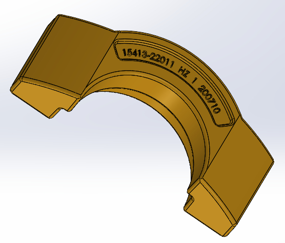
The material grade of the bearing seat casting is QT450-10, the overall dimensions are 155mm×68mm×40mm, and the main wall thickness is 25mm. The casting structure is shown in Figure 1. As the load-bearing structure of the bearing, the bearing seat needs to have high mechanical properties and internal quality, and casting defects such as shrinkage cavities, shrinkage porosity, pores, blisters, and inclusions that affect the mechanical properties are not allowed. It can be seen from the casting structure that the largest hot spots exist at the two ends of the casting, which are the key parts that require feeding.
2 Casting process
The largest cross-section of the casting is selected as the parting surface, and the casting is divided into two parts, which are located on the front and back pressure plates of the mold. According to the size of the DISA linear plate, the mold is arranged in 8 pieces, 2 rows on the left and right, and 2 layers on the upper and lower sides. It is divided into 4 groups. Each group uses a hot riser to feed 2 castings. The riser neck is set near the middle of the two hot sections of the casting to achieve the purpose of feeding the two hot sections at the same time. According to the quality of the casting and the module at the largest hot joint, the module method is used to determine the module, volume and riser neck size of the riser.[5]. A cylindrical riser is used, with a riser size of Φ60mm×90mm, and a rectangular cross-section riser neck is used, with a size of 13mm×9mm. In order to reduce the risk of defects such as sand inclusions, slag inclusions, sand washout, and cold isolation in castings, a decompression pouring system is used. In the process plan, the horizontal runner and the vertical runner are overlapped by a flat runner. At the same time, according to the designed runner size, the molten iron inlet speed at the riser neck is ensured to be less than 1.2m/s to prevent loose sand and slag inclusions entering the runner from entering the casting cavity, thereby reducing the risk of sand and slag inclusions. The cross-sectional area of the lower layer of the vertical sprue is 192mm2the upper cross-sectional area is 468mm2the cross-sectional area of the runner is 768mm2the specific parameters and template layout are shown in Figure 2. Pouring time is 6 seconds.
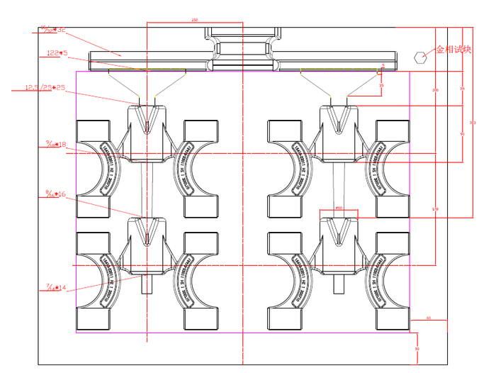 Figure 2 Process plan layout
3 Numerical simulation
After a series of process operations such as three-dimensional modeling, user definition, mesh division, and parameter setting, MAGMA software was used to conduct numerical simulation analysis of the filling and solidification process of the casting process plan.
3.1Filling process simulation analysis
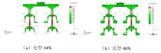
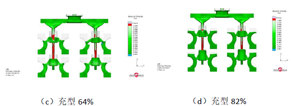
Figure 3 shows the filling speed analysis of the mold filling process. It can be seen that the entire mold filling process is very smooth, basically in line with the principle that each casting is filled with molten iron at the same time, and the filling speed in the casting cavity is lower than 1m/s. It greatly reduces the mutual thermal impact of the mold cavity during the mold filling process. At the same time, it reduces the impact of molten iron on the mold wall and reduces the risk of sand washing during the mold filling process. Figure 4 shows the temperature field at the end of mold filling. It can be seen that the temperature field of each casting is basically the same. This is also the result of each casting cavity being filled at the same time.
picture3 Filling speed analysis
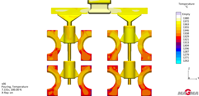 Figure 4 Temperature field simulation results at the end of molten iron filling
3.2Solidification Process Simulation Analysis
Figure 5 shows the simulation results of the solidification process of molten iron. It can be seen that the entire solidification process basically solidifies in the order from the casting to the riser. When the molten iron solidifies 80%, a small isolated liquid phase zone appears, as shown in Figure 5(c). The appearance of isolated liquid phase areas indicates the closure of the riser feeding channel, indicating that the casting may have shrinkage cavities and shrinkage porosity defects.
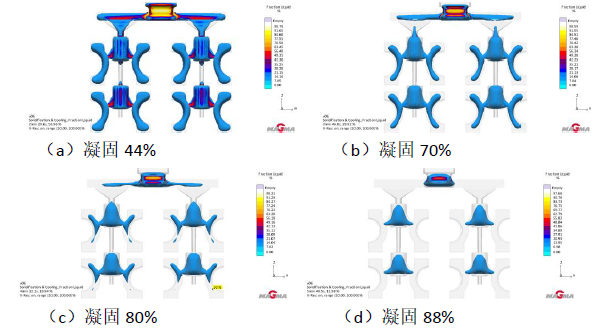 Figure 5 Simulation results of the solidification process of molten iron
Figure 6 shows the simulation results of casting hot spots, and Figure 7 shows the simulation results of casting porosity. It can be seen from Figure 6 and Figure 7 that there are tiny isolated hot spots in the parts where the isolated liquid phase area exists in Figure 5, and there is a risk of micro shrinkage defects. According to the numerical simulation results, the risk of shrinkage here is microscopic shrinkage, which can meet the quality requirements of castings. The feasibility of the process solution is high and it is worthy of trial production.
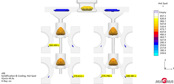
picture6 castingHot section simulation results
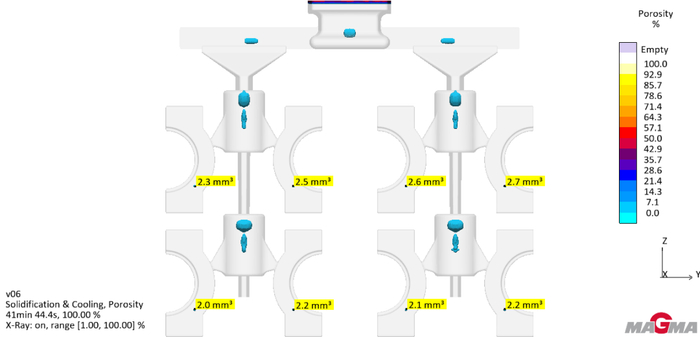
picture7 castingPorosity simulation results
4 Smelting process
According to the technical requirements, the chemical composition is controlled to w (C) 3.65% ~ 3.80%, w (Si) 2.6% ~ 2.7%, w (Mn) 0.4% ~ 0.6%, w (P) ≤ 0.06%, w (S) ≤ 0.025%, w (Mg) 0.03% ~ 0.06%. An intermediate frequency electric furnace is used to smelt molten iron. During the smelting process, the molten iron is allowed to stand at 1520~1550°C for 5~10 minutes to allow the inclusions in it to fully float, thereby achieving the purpose of reducing inclusions such as oxidized slag in the molten iron. Add 0.2% silicon carbide 5 to 10 minutes before tapping the molten iron to pretreat the molten iron to increase the number of graphite balls, reduce the probability of shrinkage defects, and prevent the occurrence of dendritic graphite. After tapping the molten iron, the spheroidizing treatment and inoculation treatment are carried out in the spheroidizing package. After the spheroidizing treatment, immediately transfer the molten iron to the pouring ladle, let it stand for 10 seconds and then perform slag pouring. The pouring temperature is controlled at 1370~1380°C. During the pouring process, a flow-based inoculant is added for secondary inoculation to ensure a good metallographic structure.
5 Production verification
Make molds according to the process plan and conduct trial production. The bearing seat produced has a smooth appearance without blisters (as shown in Figure 8). After anatomical inspection, no obvious defects such as pores, shrinkage cavities, and shrinkage porosity were found (as shown in Figure 9); the casting was inspected by 3D scanning and the dimensions met the requirements (as shown in Figure 10); the metallographic composition of the casting body As shown in Figure 11, the spheroidization rate is more than 90%, and the matrix structure is ferrite. After mechanical property testing, the tensile strength of the casting body is 491MPa, the yield strength is 325MPa, the elongation is 19.5%, and the hardness is 176HBW, which meets the technical requirements. At present, more than 15,000 bearing seats have been produced in batches, with stable casting quality and a scrap rate of less than 0.5%.
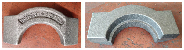 Figure 8 Actual bearing seat casting
 Figure 9 Cast anatomical verification
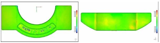 Figure 10 3D dimensional inspection of castings
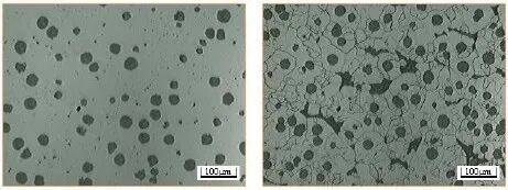 Figure 11 Metallographic structure of casting 100×
6 Conclusion
The maximum cross-section of the casting is used as the parting surface, and 8 pieces are arranged in one mold. The feeding riser is designed using the modular method. Each group uses a hot riser to feed 2 castings. A decompression pouring system is adopted. The horizontal runner and the vertical runner are overlapped with a flat runner to prevent loose sand and slag inclusions from the runner from entering the casting cavity, thereby reducing the risk of sand and slag inclusions. The filling speed is controlled below 1m/s to ensure a smooth filling process. The upper and lower castings can be filled with molten iron at the same time, effectively reducing the mutual influence of the filling process of each layer of castings. The solidification process of the casting basically realizes sequential solidification, which ensures the feeding effect of the riser and effectively prevents the occurrence of shrinkage cavities and shrinkage porosity defects in the casting.
References
[1]Du Kezhen, Zhou Yinghao. Improvement of vertical line casting process of QT600-3 rear leaf spring seat[J]. Modern Cast Iron, 2021 (2): 1-3.
[2]Ren Xianwei. Process technology and application of DISA line for producing high-quality castings[J]. Casting, 2019 (7): 777-781.
[3]Hui Chunhua. Process design of clamp castings produced by DISA line based on equilibrium solidification theory[J]. Casting, 2020(11): 1228-1231.
[4]Liu Shikui, Zhang Baoliang, Lu Xiangyu. Design and optimization of casting process for vertical DISA line production of ductile iron bottom plate castings for high-speed rail[J]. Casting, 2021(9): 1084-1087.
[5]Li Xinya. Casting Manual Casting Technology (3rd Edition)[M].Beijing: Machinery Industry Press, 2011: 190-203.